A reaming enquiry needs two hole sizes: the hole you have and the hole you need. The finished diameter describes the result, but the starting hole helps define how the tool will enter, follow the drilling path and remove the surrounding material. Quoting only the larger size leaves much of the tool selection unresolved.
The next step is to describe the job around those two sizes. Is the existing hole open and reasonably consistent? Must the tool follow it closely? What connection, drilling direction and circulation system will be used? These details turn a general request for a “hole opener” into a configuration that can be assessed against a drawing.
Start with the pilot hole and the finished hole
Record the nominal pilot-hole diameter and any known variation, obstruction or collapse. Then state the required finished diameter and its purpose, such as clearance for a following component. If the final size has an acceptance tolerance, include it rather than assuming the tool's nominal size alone defines the acceptable result.
Also describe the ground along the enlarged interval. A consistent formation and an interval containing alternating hard bands, fractures or loose material present different questions about cutting layout, guidance and removal of cuttings. A short formation description is more useful than the phrase “for hard rock” without further context.
Understand what the three descriptions mean
Integral describes an integrated tool construction. Guided describes a guiding feature or function. Modular describes an assembly made from multiple components. These descriptions can overlap: an integral tool may also have a guiding section. They should not be treated as three mutually exclusive choices.
| Your main question | Configuration to examine | Information needed for comparison |
|---|---|---|
| How are the cutting sections held together? | An integral body or an assembled construction | Assembly drawing, connection, overall dimensions and handling requirements |
| How will the tool follow the existing hole? | A configuration with a suitable guide or pilot arrangement | Pilot-hole condition, guide dimensions and the relationship between guiding and cutting sections |
| What must be checked at component interfaces? | A modular assembly | Component list, retention details, supplied parts and permitted replacement or reconfiguration |
“Modular” does not by itself mean that the cutting diameter is adjustable, or that every part is supplied as a field-replaceable spare. Those are separate features to establish from the particular design and supply scope.
Use real products to narrow the enquiry
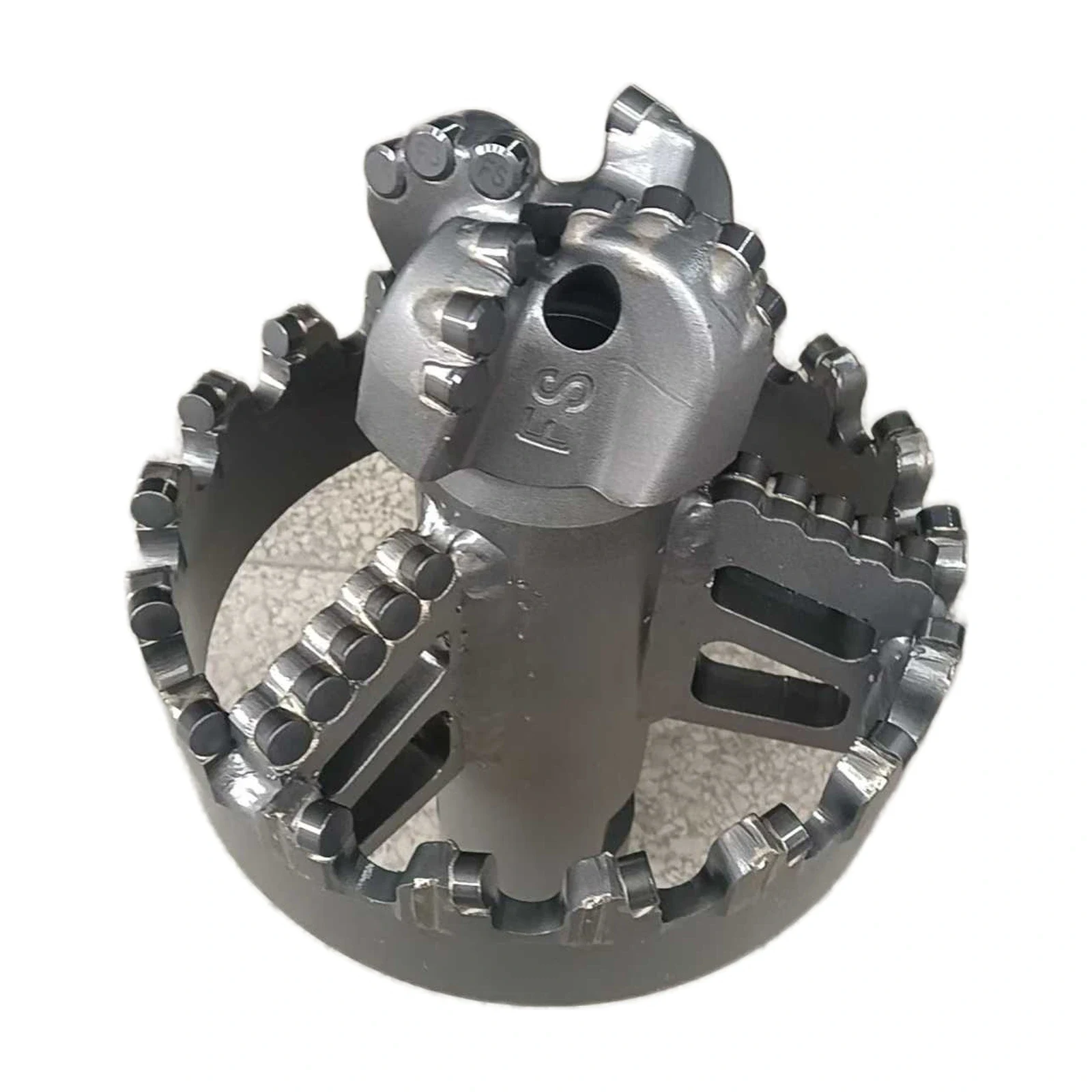
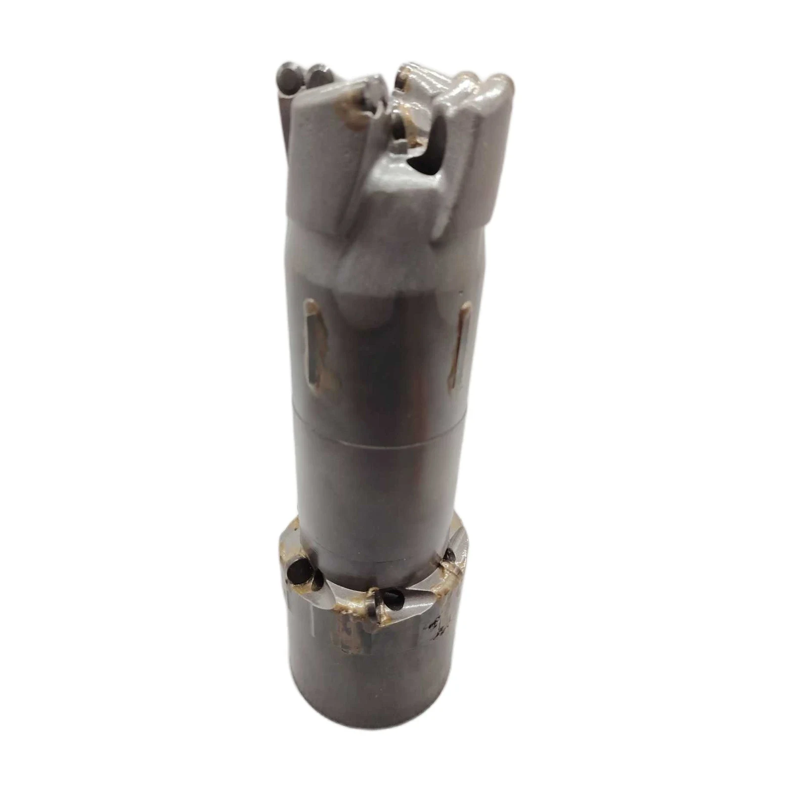
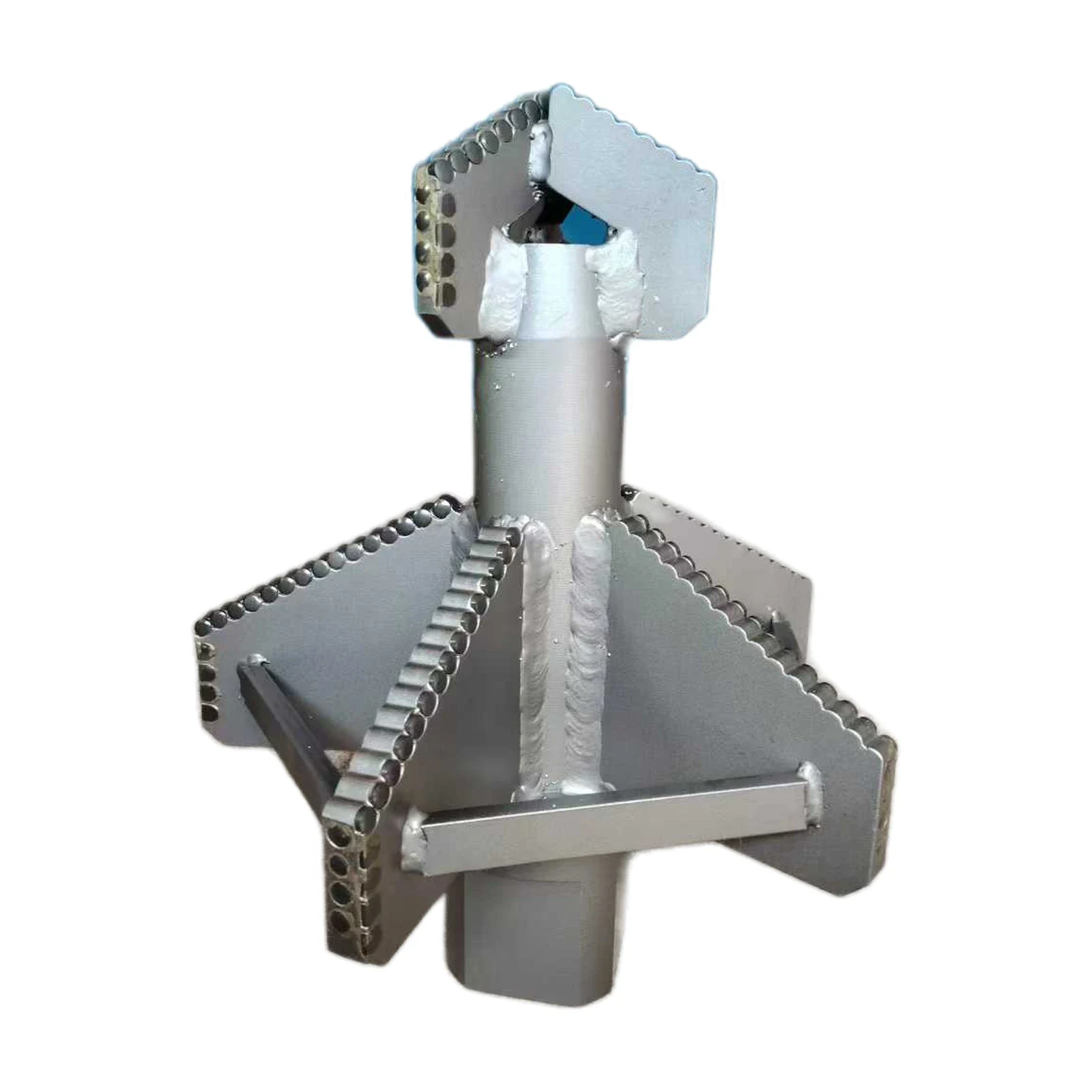
These FSDRILL products provide three starting points for discussing construction and guidance. The integral example shows stepped cutting sections; the guided example provides a reference for discussing the leading guide arrangement; the modular drag example shows an assembled layout. Use the relevant product reference when requesting a dimensioned proposal.
The series labels above identify the products. They are not a specification for a continuous diameter range, and this guide does not interpret every number in a label as a verified pilot or finished-hole dimension. Put the actual required dimensions in the enquiry even when a product name appears close to the size you need.
Check the connection and the circulation path together
A cutting layout is only part of the assembly. Provide the drill-string connection drawing or a precise, traceable connection designation, together with the rig's relevant operating limits. Indicate whether the proposed work is downward, upward or in another orientation, and state the depth or interval to be enlarged.
Explain how circulation reaches the cutting area and how cuttings are expected to return. Include the available medium and operating information from the actual system. A larger cutting envelope also requires a workable route for removed material; selection should address that route alongside the mechanical fit. A photograph cannot establish internal passages, flow requirements or the rig's ability to run the proposed tool.
Build a quotation request that can be checked
For a contractor, the enquiry should describe the immediate bore. For a distributor, it should separate the customer's job requirements from the dimensions and interfaces that must remain consistent across repeat orders. Both can use the following checklist:
- Pilot-hole size and condition, target finished size, and any acceptance tolerance.
- Formation description, depth or reaming interval, and drilling direction.
- Required guidance and any known restriction on tool length or handling.
- Connection reference and relevant rig limits.
- Circulation method, available system data and intended cuttings return path.
- Requested assembly, included components, drawing revision and inspection requirements.
If the existing hole varies substantially, describe that variation before selecting a guide size. If the assembly must pass through a restriction, supply its dimensions before choosing the cutting envelope. These details may rule out a configuration earlier than a comparison of cutter shapes would.
Compare proposals against the same job
Ask each proposal to identify its pilot or guide arrangement, finished cutting envelope, connection, assembly scope and application assumptions. This gives you comparable information even when suppliers use different product names. It also makes unresolved dimensions visible before an order is placed.
Explore the FSDRILL reaming tools range, then send the pilot-hole and finished-hole requirements with your connection reference and operating conditions. That is the practical starting point for deciding which tool configuration deserves a detailed drawing review.